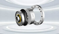
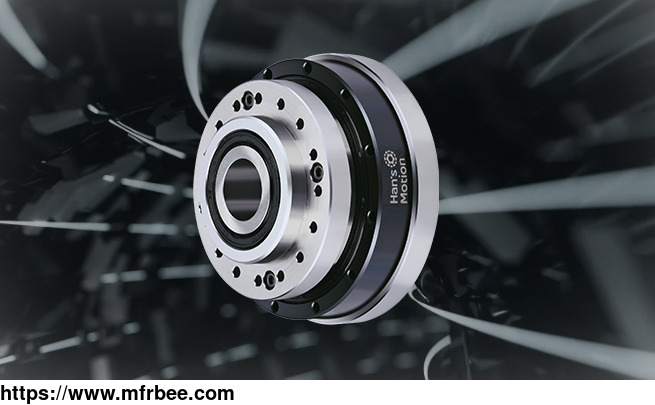
HMHG Series Harmonic Drive Hat Type
Quick Detail
- Minimum order:1
Specifications
The flexspline belongs to hollow flanging standard structure, compact design, zero backlashes, coaxial output and input, excellent positioning accuracy, and rotation accuracy. Contact harmonic
drive company Han\'s Motion for more information.
HMHG Series Harmonic Drive Hat Type List
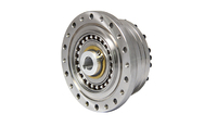
HMHG-Ⅰ Series Unit (Hollow Shaft) Harmonic Gearing
With compact hollow shaft and a robust cross roller bearing which enables the output flange to mount the loads directly without additional supports, ensuring a simple and space-saving design. Light
weight is very important for some applications, HMHG-I-LW is available for lightweight solution. HMHG-I is available in 6 size with ratios from 50:1 to 160:1.
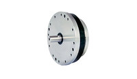
HMHG-Ⅱ Simple Unit (Flat) Series Harmonic Gearing
Input shaft connects with an inner hole of wave generator through Oldham coupling, flat shape, and standard structure
HMHG-Ⅱ-E Simple Unit (Flat & Integral Cam) Series Harmonic Gearing
Compared with HMCG-II, wave generator with integrated cam for HMCG-II-E. The integrated output cross roller bearing with high titling capacity enables the output flange to mount the loads directly
without additional supports, ensuring a simple and space-saving design. The absence of input and output flanges features a fabulous flexible design. HMHG-II is available in 6 size with ratios from
50:1 to 160:1.
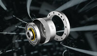
HMHG-Ⅲ Simple Unit Flat Hollow Shaft Series Harmonic Drive
High torque simplicity series with a hollow input shaft, the absence of input and output flanges features a fabulous flexible design. HMHG-III is available in 6 size with ratios from 50:1 to 160:1.
HMHS-IV Unit (Shaft Input) Series Harmonic Gearing
The integrated output cross roller bearing with high titling capacity enables the output flange to mount the loads directly without additional supports, ensuring a simple and space-saving design.
Fully sealed and easy to mount to motor. Performs fantasy on bevel gears and synchronous belt device applications.
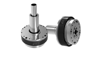
HMHG-V Unit (Hollow & Long Shaft) Series Harmonic Gearing
With input shaft can mount to motor directly. Low speed hollow shaft through supply lines, shafts or cables. Encoder can be mounted to both input and output shaft. Especially for Cobots and the
device with joint modular.
Design Guide Of HMCG Series Harmonic Drive Cup Type
In Order To Give Full Play To The Performance Of Harmonic Reducer, Please Pay Attention To The Follo
Make the input shaft, circular spline, output shaft, and shell concentric.
Wave generators can produce axial force. Please make the input shaft into some structure that can support the force.
Since the harmonic reducer is a small device that can transmit larger torque, please adopt suitable tightening torque to tighten the screw that connects the flex spline with the output shaft.
Flexspilne can have elastic deformation, so please adopt the recommended size to design the inner wall of the shell.
Input shaft and output shaft must adopt matched bearings (leave space for 2 - point support) and the structure that can bear radial load and axial load. Please do not exert too much force on the
wave generator and flex spline.
Make sure the flange diameter of the flex spline does not exceed the wheel bore diameter of the flex spline and process fillet on the flange that connects the diaphragm. Please adopt the
recommended size to design all parts.
Use a C-shape clamp ring to fix the hub of the wave generator and make sure the hook of the clamp ring does not touch the flex spline or wave generator.
Design Guide Of HMCG Series Harmonic Drive Cup Type
How Do You Calculate The Gear Ratio On A Harmonic Drive?
Calculating the gear ratio on a Harmonic Drive involves understanding the structure and components of the drive. The gear ratio is determined by the number of teeth on the circular spline,
flexspline, and wave generator. To calculate it, divide the number of teeth on the circular spline by the number of teeth on the flexspline. This ratio represents the speed reduction or
multiplication achieved by the Harmonic Drive. It\'s important to note that the gear ratio can be further influenced by the specific design and configuration of the Harmonic Drive.
What Is The Transmission Ratio Of Harmonic Drive?
The transmission ratio of a Harmonic Drive, also known as the gear ratio or reduction ratio, is determined by the number of teeth on the circular spline, flexspline, and wave generator. The gear
ratio represents the speed reduction or multiplication achieved by the Harmonic Drive. In a typical Harmonic Drive, the gear ratio can range from 30:1 to 320:1, or even higher in specialized
versions. This means that for every rotation of the input shaft, the output shaft rotates a certain number of times determined by the gear ratio. The specific gear ratio of a Harmonic Drive depends
on the configuration and specifications of the particular model, we have model for harmonic gear drive reducer, check for more information with this link.
If you want to know more types of power drive gearbox, please visit our website.